The Computer in a Nutshell
This article provides a very brief introduction to the notion of the stored program computer, or von Neumann machine, as it is sometimes called.
Before we can describe a computer, we have to say what it is. That is easier said than done because there are different types of computer and the nature of the computer has evolved over the years. For our current purposes, we can say that a computer is a device that executes or runs a program, and a program is a sequence of operations (or instructions). A computer must have three elements. First, a memory that holds the instructions. Second, a mechanism that fetches the instructions from memory. Third, a mechanism that executes the instructions. In practice, a real computer needs a fourth element; that is, an input/output device that takes in information from the outside world and delivers new information to the outside world. In the case of the personal computer, typical input devices are the mouse and keyboard, and a typical output device is the screen. In the case of an aircraft input devices may be sensors that measure speed, aircraft location, aircraft heading, aircraft pitch, and output devices may be the actuators that move the flying surfaces (rudder, ailerons, and elevator) and the power throttles.
Figure 1 describes the organization of the conventional digital computer. This is simplified (partially because there may be multiple memories, control units, and even ALUs). However, in principle, it describes the elements that all digital computers have has since the late 1940s.
Figure 1 The stored program digital computer
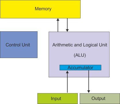
We have not mentioned data. Where does that fit into the von Neumann model? Data is the information processed by the computer; for example if you wrote a program to calculate y = p2+ q 2 we could say that the data is y, p, q, p2 and q2. All input devices convert physical quantities (e.g., moving a mouse or hitting a key) into data.
The very first computers were really (by today’s standards) calculating devices. They could receive data but there was no program in the sense that it is now used; that is, the computer performed a sequence of operations that were predetermined by the hardware of the computer and could not (easily) be changed. You may wonder why anyone would make such a computer. In the 1940s the military wanted to calculate rapidly where to point large guns in order to hit distant targets. To do this, you have to perform complex calculations that take into account atmospheric conditions and even the rotation of the earth.
The breakthrough in computer design came with the notion of the stored program. If a program is represented as data and stored in memory, you can change the data (program) and make the computer do anything you want. That is, you can program it.
The von Neumann stored program computer stores instructions in the same memory as the data used by the computer. In fact, there is absolutely no difference between data and instructions; both are just strings of bits. The only difference between instructions and data lies in how they are interpreted; in fact, one of the reasons that programs crash is because certain errors cause a computer to read data and then try and interpret it as an instruction. Even worse, it occurred to someone that you could inject data into a computer and then pass control to it (i.e., treat it as an instruction). If this data represents instructions that are harmful, we call it a computer virus.
Computers that store instructions and data in separate memories are called Harvard machines, to distinguish them from von Neumann stored program machines with one common program/data memory. Harvard machines exist today in special applications such as digital signal processing (e.g., operating with audio, video, and the analog signals you might get from an EEG or seismograph).
Fetch/execute Cycle
The von Neumann computer operates in a two-
Now, suppose that the instruction itself accesses memory; for example, consider the operation STORE r1,1234 (store register r1 in memory location 1234). In order to execute this operation, the computer has to access memory location 1234. The computer has accessed memory twice; one to read the instruction and once to access the memory location specified by the instruction. Some instructions might specify two addresses; for example MOVE 1234,2000 (move the contents of memory location 2000 to memory location 1234). In this case, there are three memory accesses: fetch the instruction, read the contents of location 2000, store the data in location 1234.
The von Neumann computer accesses memory at least once per instruction. The data path between the CPU and memory can prove to be the limiting factor in the performance of a von Neumann computer. This limitation is called the von Neumann bottleneck. A lot of the effort in computer design goes into dealing with the von Neumann bottleneck.
Summary
The stored program digital computer is also called a von Neumann machine. Its principal characteristic is that data and instructions are stored in the same memory. Instructions are executed in two phases: fetch an instruction from memory and then execute that instruction. A limitation of the stored program digital computer is the path between the CPU and memory because it has to be used by both instructions and data.
Example
It takes T seconds to read memory, P seconds to execute an instruction, and a fraction f of instructions (0 < f < 1) require one memory access, how long does it take to execute n instructions?
The n instructions each require T seconds to fetch, so the total time is nT.
Each instruction requires P seconds to execute, so the total execution time is nP
A fraction f of the instructions requires an additional memory cycle; that is, fnT in total.
The time to execute all instructions is nT + nP + fnT = n(T + P + fT) = n(P + T(1 + f)) seconds.
Components of the CPU
Before we describe the operation of a computer we need to define four terms: memory, register, ALU and bus.
Memory
Information in a computer (both instructions and data) is stored in its memory which
is sometimes called main memory, immediate access memory, or main store. In the PC
world, this memory is frequently called DRAM (because it’s made from DRAM chips).
The memory is called immediate access memory because data is immediately available;
unlike in secondary memory (e.g., hard drives, CDs, DVDs, tape) where data can take
a relatively long time to access. Note that when we say ‘immediately available’ the
comparison is being made with disk drives which are millions of times slower. In
reality, it might take 50 ns (i.e., 50 x 10-
Main store can be described formally as, ‘Random access, read/write memory’ which means that the time taken to access a stored element at any random location is constant and that you can read data from it or write data to it.
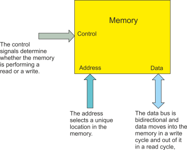
Figure 2 illustrates memory conceptually. It has three ports (a port is a point of connection). An address port that contains the address (location) of the data to be accessed, a data port via which data enters the memory or leaves the memory, and a control port that determines the operation of the memory – read or write.
The address port has n bits which means that 2n different locations can be accessed. If there are 8 address lines, these can express all the 28 = 256 values from 00000000, 00000001,00000010, … , 11111110, 11111111. A memory chip might have 24 address lines allowing 224 locations to be accessed.
The data port is bidirectional because data flows into memory during a write operation,
and out of memory during a read operation. The width of a data port is typically,
1, 4, 8, of 16 bits. If you want to implement a computer with a 64-
Figure 2 Memory
The capacity of a memory (total number of bits) is given by the number of locations multiplied by the number of bits stored at each location. The result is normally expressed in bytes. Below are several example. The total capacity of the memory is expressed in KB, MB, GB (or even) TB. However, you have to be careful. Traditionally, the K in memory terminology represents 1024 (i.e., 210) so that 8,388,608 is expressed as 8M bytes. However, some use the decimal 1,000 as K and express 8,388,608 as 8.3K (because it looked bigger).
Example
Chip Locations Capacity (bits) Capacity Capacity
8 address lines 16 data bits 28 = 256 256 x 16 = 4,096 512 ½K
16 address lines 1 bit 216 = 65,536 65,536 x 1 = 65,536 8,192 8K
24 address lines 4 bits 224 = 16,777,216 16,777,216 x 4 = 67,108,864 8,388,608 8M
The control port of a memory included the signals that select (activate) the memory and determine whether data is to be written into it or read from it.
In a high-
Registers
The register is a single memory location. You can regard is as a memory that is m-
Registers are the fastest storage locations in a computer and are used to store temporary data during the fetching and executing of an instruction.
Buses
A bus is a data highway that connects registers, memories, and functional units such as ALUs (and even I/O devices). Although many devices can be connected to a bus, only one device at a time can put data on a bus. However, multiple devices can read data off a bus simultaneously.
The ALU
The ALU or arithmetic and logic unit is the device where data processing takes place.
It has four ports. Two input ports that access two m-
The Processor
We can now build a computer. Figure 3 illustrates the structure of a very simple stored program computer.
Figure 3 Structure of a computer
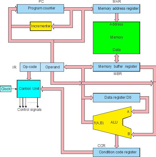
In figure 3 the registers are in blue, the buses in pink, the functional units are in yellow, and the memory in green. We are going to explain the operating of this computer step by step.
Fetching the Instruction
We begin with the register called the program counter, PC. This register contains the address of the next instruction to be executed. The name program counter is rather unfortunate because it is misleading. This should be called ‘next instruction pointer register’ but we are stuck with program counter.
The contents of the program counter are fed to the register called the memory address register, MAR. This register holds the address of the next location in memory to be accessed.
We can express the operation “copy program counter to memory address register” as
[MAR] ¬ [PC]
[MAR] ¬ [PC]
Once the program counter has been used to access an instruction, it must be incremented to point to the next instruction; that is,
[PC] ¬ [PC] + 1
In the next step, the instruction must be read from memory. In this computer, it is copied into the memory data register that holds all data from memory or that is going to be written into memory. We can write this as:
[MBR] ¬ [M[MAR]]
The expression is read as “the contents of memory whose address is given by the contents of the memory address register”.
Finally, the contents of the memory data register are copied to the instruction register, where the instruction is held while it is being decoded and executed. We can write
[IR] ¬ [MBR]
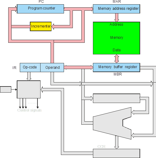
Putting all these together, we can express the fetch phase as:
[MAR] ¬ [PC]
[PC] ¬ [PC] + 1
[MBR] ¬ [M[MAR]]
[IR] ¬ [MBR]
Figure 4 Parts of the computer taking place in the fetch phase
Once the instruction (the op-
Instruction Formats
Before we can demonstrate how the computer of figure 3 executes and instruction, we have to introduce the notion of instruction formats; that is, how a computer instruction is formatted (i.e., structured).
Instruction formats are generally (and loosely) categorized by the number of addresses;
for example, one-
Three-
A typical arithmetic operation is p = q + r which requires three operands p, q, and
r. Consequently a 3-
If an operation is specified by 8 bits, and each operand address requires 32 bits,
the total length of an instruction is 8 + 3 * 32 = 8 + 96 = 104 bits. Such an instruction
length is not practical. Consequently, three-
Two-
A two-
Destination = destination + source
The two-
One-
A one-
The machine of figure 3 is a one address machine. We’ve chosen this structure because it is the simplest way of illustrating the structure of a computer and the operation of a fetch execute cycle.
In order to illustrate the execute phase we have to demonstrate an actual instruction because the process is different for each instruction. Let’s use ADD 1234 (add the contents of memory location 1234 to the accumulator).
We begin with the instruction ADD 134 in the instruction register. Figure 5 shows the parts of the CPU used in the first part of the execute phase. The operand address (i.e., 1234) is sent to the memory address register and latched. Now it can be used to access the actual operand in memory.
Figure 5 The execute phase (part 1)
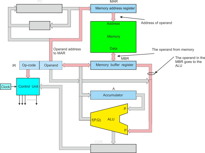
The operand is read from memory and fed to the memory buffer register where it is latched. We can write this in RTL as:
[MAR] ¬ [Operand]
[MBR] ¬ [M[MAR]]
Now the memory buffer register contains the actual data to be used in the operation. The memory buffer register is connected to the P port of the ALU.
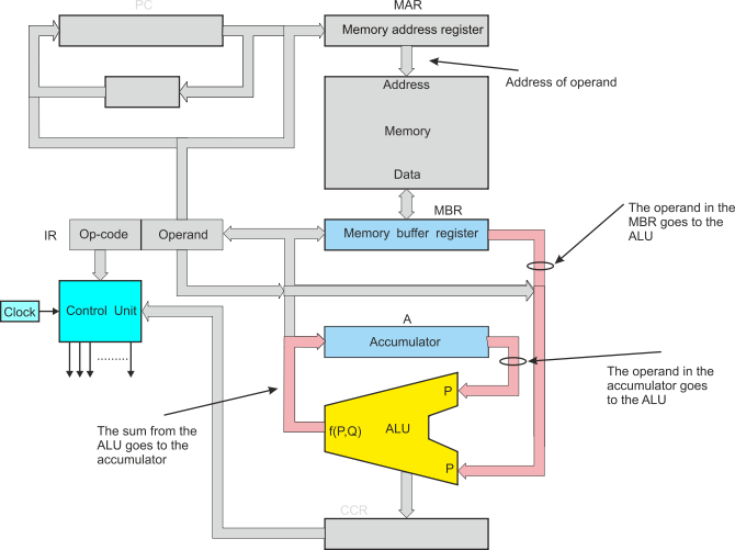
The instruction is decoded and the control unit sends the appropriate code for ADD to the ALU. The contents of the accumulator are fed to the ALU. Now the data from memory and ALU are added together and the result sent to the accumulator, figure 5.
The full RTL for the addition is:
[MAR] ¬ [Operand]
[MBR] ¬ [M[MAR]]
ALU ¬ [MBR]
ALU ¬ [A]
[MBR] ¬ ALU
Note that the ALU does not have square brackets because it does not store data. The actual operation implemented is
[A] ¬ [[A] + [MDR].
Figure 6 The execute phase (part 2)
The control signals generated by the control unit are: enable a register onto the bus, clock data off a bus into a register, set the memory to read or write, and select the ALU function.
So far, we have demonstrated how the computer performs data processing. The same process would implement:
Store accumulator in memory
Load accumulator from memory
Add (or any other operation) data to the accumulator
Add (or any other operation) data in the accumulator to memory.
There are only three element missing: literals, pointer-
We cannot deal with literals yet (e.g., ADD #5 which adds the literal value 5 to the accumulator to implement [A] ¬ 5. In practice this is easy because there is a path between the IR and the MBR; that is, the actual or literal operand can be fed from the IR directly to the MBR. The operation ADD #5 is therefore:
[MBR] ¬ [Operand]
ALU ¬ [MBR]
ALU ¬ [A]
[A] ¬ ALU
Pointer-
Conditional Behavior
We cannot implement the conditional branches such as BEQ XYZ (branch on zero to instruction XYZ). Conditional branches are necessary to implement if…then…else statements, and for, while, and repeat loops.
In order to implement a conditional operation, register Is connected to the ALU to receive the Z,N,V,C (zero, negative, overflow, and carry) flags from the result of an operation. These flag bits are stored in the CCR (condition code register) which is also called the status register or flag register.
The appropriate flag are tested to implement an operation such as branch on zero or branch on greater than. Then, the result of the test is used to load the program counter with either its next sequential address or the branch target address. Consider, BEQ XYZ (branch on zero to XYZ). In RTL this is simply
IF Z = 0 THEN [PC] ¬ [PC] ;if not zero then continue
ELSE [PC] ¬ [IR] ;else load the target address
Points to Understand and Remember
- What is the difference between memory and a register?
- What determines the width of a register?
- What are the advantages of storing data in registers compared with memory?
- What are the disadvantages of storing data in registers rather than memory?
- What is a bus and how is it used in a computer?
- What are the advantages of the two-
phase fetch/execute mode on instruction processing at the heart of the von Neumann machine? - What are the relative advantages and disadvantages of 1-
, 2- , and 3- address machines? - A computer executes the operation [A]¬ [A] + [M[A]]. Explain what this operation achieves.
- Suppose you design a computer with a 2-
address instruction. There are to be a minimum of 200 different operations. Although there are two addresses, you cannot specify two memory addresses in the same instruction. Consequently, an instruction can be one memory address and one register, or two registers. The computer is to have 16 registers and up to 2048 addressable memory locations. What is the minimum size of an instruction word? - You construct a memory array that provides 128 Mbytes of memory. The computer’s data
bus is 32 bits. If you use 1-
bit memory devices with a 20- bit address bus, how many chips are required to implement the memory array? - What is the condition code register in a CPU and how is it used?
- What is the difference between a von Neumann architecture and a Harvard architecture. Why do you think that a Harvard architecture might be better at avoiding computer viruses?
- Suppose the computer of figure 3 is able to move data from one point to another in 2 ns, the ALU takes 10 ns to perform an operation, the incrementer takes 5 ns, and the memory has an access time of 20 ns. How long does it take to execute an ADD 1234 instruction?
The Memory Wall
Year by year, computers get faster. The rate at which processors execute instructions has increased, with higher clock speeds, better semiconductor technology, pipelining, and superscalar processing.
Memory (DRAM) has also been getting faster; for example, DDR1 chips have been replaced by DDR2 and then DDR3 chips.
However, the speed of the CPU has been increasing at a greater rate than that of memory. Consequently, computers have to wait for the memory to fetch data and instructions. The growing gap between processor cycle time and memory access time is called the memory wall and some believe it to be the ultimate limit to the increase in processor performance.
Computers reduce the effect of slow memory by putting frequently used data in very fast memory called cache memory. In general, over 90% of memory accesses are to cache rather than to DRAM.
Register Transfer Language
Register transfer language, RTL, is used to define operations in a computer in an
algebra-
Square brackets indicate the contents of; for example, [A] means the contents of the accumulator.
The back arrow, ¬, indicates data transfer; for example, [P] ¬ [Q] means that the contents of Q are copied to P.
The notation [MAR] ¬ 0 means that the actual literal value 0 is written into the memory address register.
If [M] means the contents of the memory and [MAR] means the contents of the memory address register, then the notation [M[MAR]] means the contents of memory whose address is in the memory address register.