Loaded Transmission Lines
In an ideal world, all loads on buses would be purely resistive; that is they would appear only as a resistance. In practice, anything you connect to a bus (e.g., an input or an output circuit) loads the bus capacitively. The effect of these capacitive loads is to modify the characteristic impedance of the bus itself. In other words, if you connect a circuit to a bus you are going to alter its electrical characteristics.
Suppose that ZO is the unloaded characteristic impedance of a transmission line (i.e., a bus). The value of ZO is can be calculated from the expression ZO = Ö(L/C), where L is the line’s inductance per unit length, and C is its capacitance per unit length. We can also calculate the propagation speed of a signal on a transmission line from the formula 1/Ö(LC). Unfortunately, it’s difficult to measure the values of L and C directly. However, you don’t have to know the values of C and L for a bus¾you can calculate the characteristic impedance of a bus if you know its physical dimensions and the dielectric properties of the material that separates the two bus lines. How you do this is beyond the scope of this text and is found in texts on transmission line theory. The impedance of a bus can be measured with a laboratory instrument.
When capacitive loads are connected to a bus, its impedance changes and the bus has
a new or loaded impedance which is written ZO’. The value of ZO’ can be calculated
by means of the expression ZO/Ö(1 + Cd/CO). The formula for the loaded impedance
of a transmission line indicates that ZO’ is lower than ZO. In this equation, Cd
is the distributed capacitance of the bus caused by the devices connected to the
bus and is measured in Farads per unit distance. Typical devices have a loading of
about 5 to 10 pF (1 pF = 10-
CO is the intrinsic capacitance of the transmission line and is very difficult to measure directly. Fortunately, we can calculate the value of CO by means of the expression CO = tPD/ZO, where tPD is the is the propagation delay of the transmission line per unit length. The propagation delay can easily be measured in the laboratory.
The speed of signals on a loaded bus are reduced by the effect of the loading. The propagation delay of a loaded transmission line, tpd’, is given by:
tpd’ = tpd. Ö(1 + Cd/CO).
We can summarize the key formulae you might use when designing a bus as:
Loaded impedance Zo/Ö(1 + Cd/CO)
Intrinsic capacitance CO = tPD/ZO
Propagation delay tpd’ = tpd. Ö(1 + Cd/CO)
Reflection coefficient unloaded (ZL -
Reflection coefficient loaded (ZL -
Example
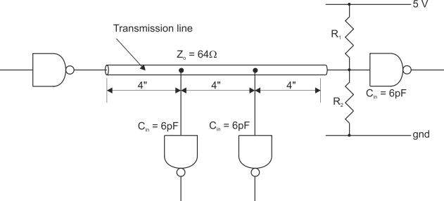
The following example is taken from a Signetics application note. Figure 1 shows a 12” bus with an unloaded impedance of 64 . Three input circuits are connected to this bus, each of which presents a 6 pF load. The propagation delay of the unloaded bus is quoted as 1.77 ns/ft.
The first step is to calculate the bus’s intrinsic capacitance CO, which is given by:
CO = tPD/ZO = 1.77 ns/ft ¸ 64 = 2.30 pF/inch. We can now calculate the loaded impedance of the bus because we know its unloaded impedance (64 ), CO (2.30 pF/inch), and Cd (18 pF/12” = 1.5 pF/inch).
Zo’ = ZO/Ö(1 + Cd/CO) = 64 Ö(1 + 1.5/2.3) = 49.8 The loaded impedance is appreciably less than the unloaded impedance.
Suppose that the terminating resistors have been designed to provided a termination of 64 to match the bus’s characteristic impedance. The effect of loading the bus is to create a termination mismatch whose reflection coefficient is given by:
(ZL -
FIGURE 1 Distributed loads connected to a bus
This result tells us two things. The first is that you should terminate a bus by its loaded impedance rather than its unloaded impedance (this might be difficult to do in practice because the bus designer has little control over the characteristics of devices that are connected to the bus). The second is that it is important to minimize the capacitive loading of input and output devices connected to the bus.