A Sequence Detector
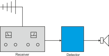
Let’s take a look at a sequence detector using a state machine. Consider a radio designed to detect automatically an SOS signal and sound an alarm when an SOS is received. Figure 1 illustrates the structure of the hardware. The receiver is tuned to a station that transmits a sequence of characters, and the output of the receiver is fed to the detector. The detector contains a computer that reads in characters, one by one from the receiver, and generates an alarm when the sequence “SOS” is selected. For example, the detector will generate an alarm when the sequence WNFENCKGKLESOS is received, because it includes the characters SOS.
Figure 1 An SOS detector
So, where do we start? There’s no right way to generate algorithms. Programmers employ a mixture skill, initiative and expertise. The problem we have devised is very similar to one we used to introduce the processor in Chapter 1.
One way of tackling a problem like this is to imagine that the system is always in one of several states; for example, a person might be in one of the states: sleeping, working, eating, or resting. In this case, when a character is received from the radio the detector must be in one of three states:
- it has not yet located the start of the sequence it is looking for
- it has located the start of the sequence and is somewhere in the sequence
- it has located the end of the sequence.
We can deal with a system that exists in several states by constructing a state diagram
that illustrates each of the states, and explains how a transition between states
is made. Figure 2 provides a partial state diagram for this problem. A state is shown
as a circle. In figure 2 there are two states, S0 and S1. The system must be in one
(and only one) of the states at any time. The lines between states show how a change
is made from one state to another (the label on the line indicates the event that
causes the change-
Figure 2 Detecting the beginning of a sequence
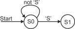
Assume that, initially, the detector is in state S0, corresponding to the start of the sequence has not yet been located. When each new character is received two things can happen—either the character is not part of the sequence we are looking for, or it is the first character of the sequence (i.e., the letter ‘S’).
Figure 2 shows two paths leading from state S0. One is from state S0 back to state S0 and is labeled not ‘S’. This path is taken when any character apart from a letter ‘S’ is received, and results in no overall change of state. In other words, if the system is in state S0 and, for example, an ‘A’ is received, the next state is also S0. The other path, labeled ‘S’ in figure 2, indicates a change from state S0 to state S1. The detector enters state S1 when an ‘S’ is detected, which corresponds to the state the initial character of the sequence has been detected.
When the system is in state S1 and a new character is received, one of three things can happen. If the character is neither an ‘S’ nor an ‘O’, we can’t be in the sequence ‘SOS’ and must go back to state S0. If the character is an ‘S’ we may be at the start of an ‘SOS’ sequence and must remain in state S1. If the character is an ‘O’, we have detected the sequence ‘SO’ and can move to state S2—figure 3.
Figure 3 Building up a state diagram to detect the sequence SOS
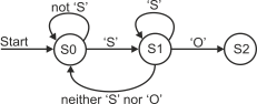
Table 1 provides a transition table for the states in figure 3. The transition table gives the current state, the new character, and the corresponding next state.
Table 1 Transition states for figure 3.
Current state Next character Next state
S0 S S1
S0 Neither S nor O S0
S1 Not S S0
S1 O S2
S1 S S1
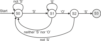
When the system is in state S2, the reception of an ‘S’ leads to state S3 (i.e., the detection of the sequence ‘SOS’), and the reception of any other character leads to state S0. The final version of the state diagram is given in figure 4.
Figure 4 The complete state diagram to detect the sequence SOS
The Flowchart
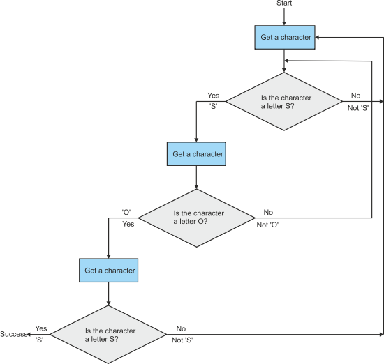
We can employ another technique to generate a solution to this problem—the flowchart . A flowchart provides a graphical representation of an algorithm and consists of three components: boxes that describe actions; diamonds that describe conditional operations; and lines that show the flow of control. Figure 5 provides a flowchart for this algorithm.
Figure 5 is read from top to bottom beginning at the point labeled “start”. The first
action indicated by the box labeled Get a character is to read a character from the
receiver. This action takes you to the top-
A flowchart can provide an excellent graphical illustration of relatively simple algorithms. Although the flowchart was widely used in the 1970s to describe even complex algorithms, its use was frowned upon in the 1980s. Today, it’s almost invisible. Flowcharts grow both large and confusing once the algorithm becomes even moderately complex. However, the pendulum has swung back a little and the flowchart is becoming almost respectable again in some quarters. In this example, I find the state diagram both more elegant and clearer than the flowchart.
Figure 5 Flowchart for an ‘SOS’ sequence detector